Sully Station Technologies
Home Circuit Library Datasheets Contact

Parts, tools and supplies for the electronics experimenter.

74HC139 Decoder Circuit

  • Concept of Operation

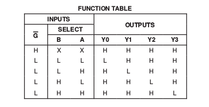
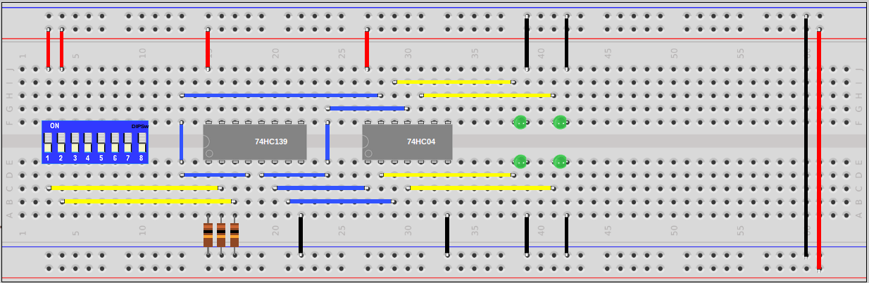
    The SN74HC139 (74139) IC provides two individual 2-line to 4-line decoders in a single package. The decoders take as input a two digit binary number 1 thru 4 (00, 01, 10, 11) and output by selecting one of four lines. This SN74HC139 example circuit uses the first decoder on pins 1-7. Inputs are pins 2 and 3, and the outputs are pins 4 to 7. Pin 1 is the enable. If the enable is inactive then no outputs are active regardless of the state of pins 2 and 3. The pinout and functional output table from the SN74HC139 datasheet are provided below.

    The SN74HC139 is an active low device, meaning that for both the inputs and the outputs, a low voltage indicates logic 1 and a high voltage indicates logic 0. The example circuit uses LEDs to indicate which of the four output lines is active. A SN74HC04 (7404) hex inverter is used to invert each of the outputs, converting the active low logic to active high logic, and illuminating the LED fed by the active output.

  • Schematic

  • Breadboard Diagram

  • Parts

    • SN74HC139 - Dual 2-line to 4-line Decoder IC (x1)
    • SN74HC04 - Hex Inverter IC (x1)
    • 10K Resistor (x3)
    • Green 5v LED (x4)
    • 8 Position DIP Switch (x1)

    (All parts for the project are available in our store.)

  • Function Table for the 74139 Decoder

  • SN74HC139 Pinout

  • SN74HC04 Pinout

  • Notes on Implementation

    1. In the schematic unused switches on the 8 position DIP switch are not shown. Refer to the board diagram for placement of the DIP switch.
    2. Be mindful of the notch on the IC package which indicates proper orientation of the device.
    3. The schematic symbols for the IC logic gates with multiple gates per chip are noted with A, B etc. to designate the different gates on the same chip.
    4. The LEDs used in the project have a built in current limiting resistor eliminating the need for an external resistor to protect the device. This resistor is shown in the schematic as a resistor with the value “Lim” for completeness.
    5. The circuit was built and tested at 4.8 volts DC (4 AA NiMH rechargeable batteries). The 74HCxx series ICs are rated from 2 to 6 volts.