
Parts, tools and supplies for the electronics experimenter.
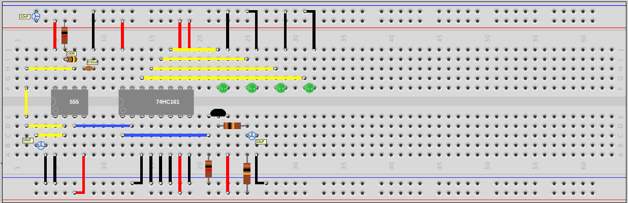
The SN74HC161 (74161) integrated circuit is a synchronous 4-bit binary counter. In this example circuit, the counter is setup in its most simple configuration. It counts from 0 (binary 0000) to 15 (binary 1111) and then rolls over to 0 and starts the count again. The binary output is displayed on four LEDs.
An NE555 integrated circuit is used to drive a clock signal. The NE555 is a configurable timer. Here it is setup in asynchronous mode, outputing a steady stream of pulses at a frequency of about 1.3Hz (one pulse every 1.3 seconds). The output of the NE555 is connected directly to the clock pin of the SN74HC161 which increments on every rising pulse.
The SN74HC161 is quite versatile, with features to preset numbers, enable and disable counting, and a rollover output that facilitates chaining multiple SN74HC161s together. Here these features are not used. The four inputs for preset are tied to ground to keep them from floating, and the load and enable pins (which are activated by a low signal) are tied high to keep them inactive. The rollover pin is left unconnected.
One feature which is used is the clear capability which sets the counter to zero. A resistor-capacitor delay circuit is placed between the positive input and the SN74HC161’s clear pin. This delay keeps the clear pin low for a moment when power is first applied to the circuit which activates the clear and ensures the count starts at zero.

(All parts for the project are available in our store.)

