
Parts, tools and supplies for the electronics experimenter.
The half adder circuit performs binary addition on two one-bit binary inputs. The output of the circuit are the sum and the carry bits.
In binary addition:
0 + 0 = 0 (sum = 0, carry = 0)
0 + 1 = 1 (sum = 1, carry = 0)
1 + 0 = 1 (sum = 1, carry = 0)
1 + 1 = 10 (sum = 0, carry = 1)
The logic of this process expressed as a truth table is:
| Input | Output | ||
|---|---|---|---|
| A | B | Sum | Carry Out |
| 0 | 0 | 0 | 0 |
| 0 | 1 | 1 | 0 |
| 1 | 0 | 1 | 0 |
| 1 | 1 | 0 | 1 |
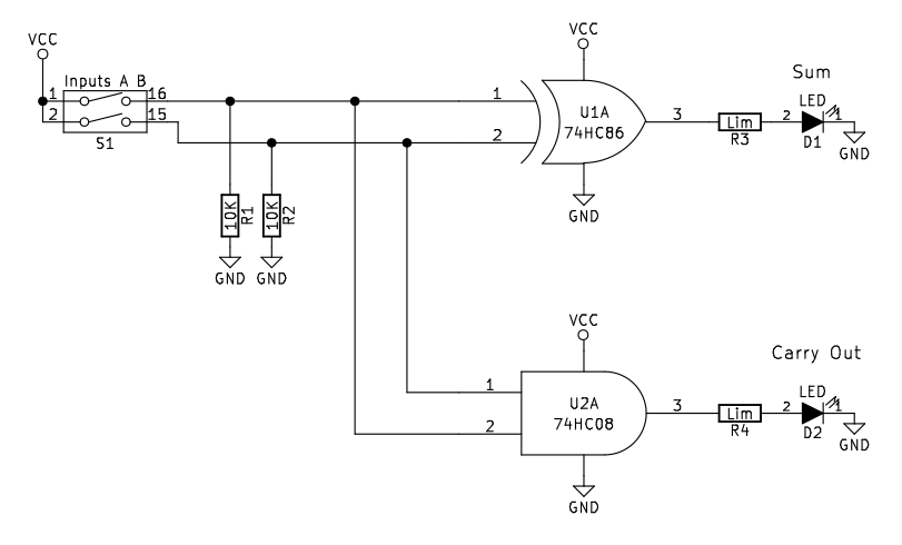
Observe that the sum bit is equivalent to the Exclusive OR (XOR) operation: if A or B is 1 the output is 1, but if both A and B equal 0 or 1 then the output is 0.
Observe also that the carry bit is equivalent to the AND operation: if both A and B are 1 then the output is 1, otherwise the output is low.
The half adder circuit performs the operation by routing the A and B inputs to both a XOR gate and an AND gate.The half adder is implemented here using 74HCxx series high-speed CMOS digital logic ICs: the SN74HC86 (7486) and SN74HC08 (7408).

(All parts for the project are available in our store.)

