
Parts, tools and supplies for the electronics experimenter.
An electronic NAND gate performs the digital logic NAND function. The output is only low when both of the two inputs are high. When either or both inputs are low, the output is high.
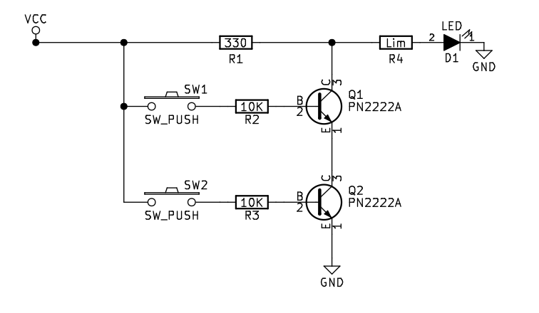
The example transistor NAND gate circuit is implemented here using PN2222A NPN transistors (a variant of the 2N2222A) but many common NPN bipolar junction transistors could be substituted.
The gate is built from two transistor switch circuits wired in series. The inputs to the NAND gate are two manual push button switches each of which drives a transistor. This circuit is nearly identical to the transistor AND gate. However, by designing the circuit such that the output is taken at a voltage divider between the transistor and the positive voltage, the NAND circuit has an inverting component. When either of the transistor switches is off, the resistance across the two switches is large, the voltage at the output is high and the LED is lit. When both transistor switches are on, the resistance across them becomes very small, the voltage at the output is low and the LED is off.

(All parts for the project are available in our store.)
| In | Out | |
|---|---|---|
| 0 | 0 | 1 |
| 0 | 1 | 1 |
| 1 | 0 | 1 |
| 1 | 1 | 0 |
