
Parts, tools and supplies for the electronics experimenter.
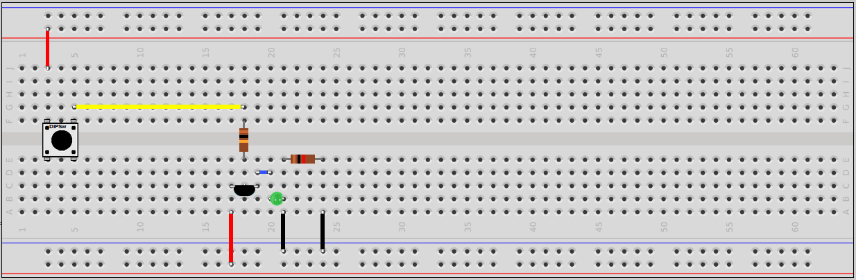
The circuit demonstrates the use of a transistor as a switch. The transistor switch is implemented here using PN2222A NPN transistor (a variant of the 2N2222A) but many common NPN bipolar junction transistors could be substituted.
The transistor is setup in what is known as the common emitter configuration. In this configuration, an input applied to the transistor base results in a voltage and current flow across the collector-emitter junction that is proportionate to that input. The pinout for the PN2222A transistor appears in the section below. The pins are labeled E (emitter), B (base), and C (collector).
Common emitter circuits are often used for amplifiers, where an analog input at the base, such as a radio signal, results in a proportionate yet larger output. However when used as a switch, the circuit is designed such that the transistor is either fully-on or fully-off.
In the transistor switch presented here, the state of the circuit is controlled by a manual push button switch. When the switch is open, there is no current at the base of the transistor and therefore the collector current is effectively zero and the transistor is said to be in cutoff state or fully-off. When the switch is closed, there is maximum current at the base and therefore maximum collector current. The transistor is said to be saturated or fully-on.
The output of the circuit is the seen in voltage present to the LED between the transistor and the 1K resistor connecting the circuit to ground. The transistor functions here as a variable resistor forming a voltage divider with the 1K resistor. When the transistor is in cutoff, the resistance of the transistor is extremely high, the voltage at the LED is effectively zero and it is dark. When the transistor is saturated, its resistance becomes very low, a high voltage is present at the LED and it is lit.

(All parts for the project are available in our store.)
| In | Out | |
|---|---|---|
| 0 | 0 | |
| 1 | 1 | |
